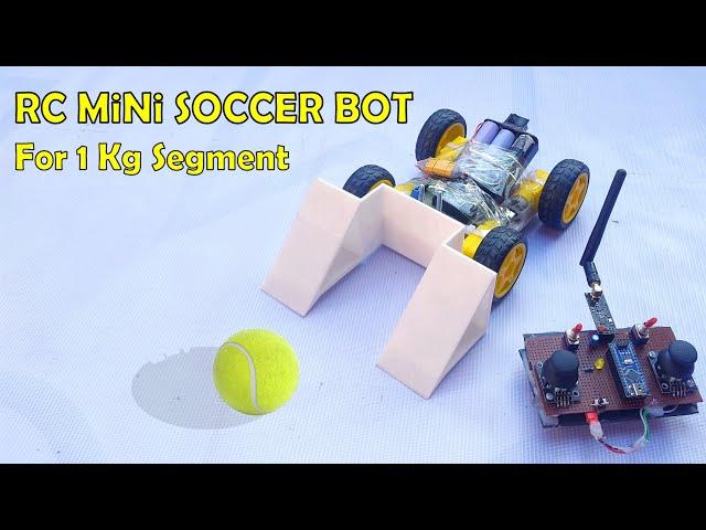
How to Make RC Mini Soccer Bot using nRF24L01 and Arduino
Комментарии:

wouldn't it be better using an esp32 as the microcontroller instead of arduino nano?
Ответить
code was error
Ответить
Please which software do you use to create model 3D of the car all electronic circuit ?
Ответить
Bro apporax cost of this project???? To do or buy..
Ответить
how many volts of battery do you use
Ответить
Why is the code in the video different from the one in the link?
Ответить
im sorry,what is the function of the push button?
Ответить
if you use 3,5V why need buck coverter?
Ответить
How if meet crossroads or t junction?
Ответить
Hi! This a great video and we're currently doing this one. Can I ask for the code or perhaps may you be able to give me what comes next in void PID_reading()? Thanks a lot!
Ответить
Want circuit diagram please help sir ........😢
Ответить
Thanks for making this vid , can you explain to me how to make the line follower turn left or right.I did by following your code with 8 channel but it can turn left or right.And again to say thanks for making this vid🥰🥰🥰🥰
Ответить
Hello guys
Could you help me to make connections correctly please...???

can i able use qtr 5 array sensor ???
Ответить
If you use a 1000 rpm motor would you need to adjust the code?
Ответить
Can I get design of this robot? Which you made by EasyEDA
Ответить
Where did you buy the components from? Which website? Can you share the link?
Ответить
Can you please share the specification of Buck and boost converter
Ответить
I have this annoying issue.
S3, or the middle sensor, is the only sensor that's able to detect the contrast between black and white. Basically it's the only sensor that detects the line. The other sensors (S1, S2, S4 and S5) do not detect the contrast between black and white, and instead output 0 if it detects nothing (I face it away from anything or high up in the air) and 1 if it is in close proximity with anything, regardless of contrast or colour. Please help!
Note: I'm using a TCRT5000 5-channel Line Tracking Module. It should still essentially work.

Hello sir but why the circuit is not opening and i have already subscribed you
Ответить
Can i use 5 channel array?
Ответить
Will it avoid obstacle?
Ответить
I want to ask about the PID values. I mean don't they need to be adjusted first? Or this code will automatically adjust them. Kindly answer the question. I am making a LFR using the PID algorithm. Everything is good. Just the movement is not smooth, probably calibration of PID.
Ответить
bro, my motors are not getting enough power...what could be the problem??
Ответить
What are the components?
Ответить
Brother please share the circuit diagram you developed in easyeda
Ответить
Can I get some suggestions from you? I want to make LFR for a competition. Since I'm making it for the 1st time I need some help. How can I contact you?
Ответить
Can not unlock code .. I subscrube but not get code
Ответить
will this work with 200 rpm n20?
Ответить
can it follow a star the star which has intersections
Ответить
i can't use the push button in this circuit.. could please provide me the resources for using push button ?
Ответить
Could you please tell the components and the overall price it would cost me?
Ответить
hello can you make a sumobot using 8 qtr rc distance sensor?
Ответить
sir can you we use arduino uni instead of buck convertor and
boost convertor

sir and can we buy the robot from you also . this line following robot
Ответить
only one motor is working when i press button 1 please help i have competition in 2 days please reply fast
Ответить
Hello sir... Can I get the full name of those components...?
Also for t connector, xt60 or xt90 is ok...?

But I use arry sensor
Ответить
Please help me
Ответить
sir how to change code suc that it priortises left middle or right turns over others in case of inter section
Ответить
can yo make seprate vido on how to calibrate this
Ответить
how did you make hole and cut vero board
Ответить
I would love to know your opinion!! in the components I picked for my robot line follower with obstacle navigator
Li-po 12v battery
• N20 motors
• Two Rubber wheels
• One free moving ball caster wheel
• Esp32 (WROOM-32)
• TB6612FNG motor driver
• 5 array IR sensor (TSM-5-E)
• GY-53 (VL53L0X obstacle sensor)
• Voltage Regulator: LM2596 DC-DC Buck Converter

Sir can we use 7 arry sensor
Ответить
Also sir can we use dot board instead of vero board...?
Ответить
Please help me
Ответить
I have made the same project but my robot is only rotating 360. Degree its not following the line. I have also checked the motor directions they are also fine the robot moves clockwise and anticlockwise
Ответить
Sir. Motor N20 is 6V or 11V?
Ответить
where is te QTR sensor array code??
Ответить


