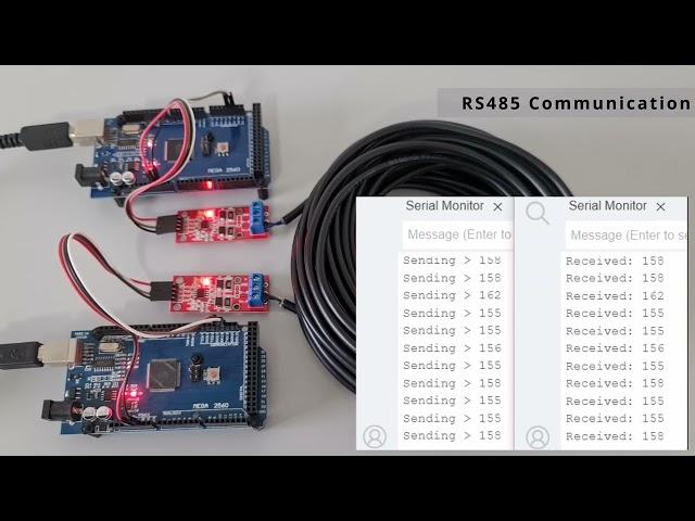
RS485 and Arduino Mega Serial Communication
The TTL to RS485 module facilitates communication between two Arduino Mega boards by converting the TTL (Transistor-Transistor Logic) serial signals from the Arduino boards into RS485 signals, which are more suitable for long-distance communication. Here's how it works:
- TTL Serial Signals: Arduino boards communicate with each other using TTL serial signals, which operate at logic levels of 0V for "low" and 5V for "high." However, TTL serial communication is limited in distance due to signal degradation over long cables.
- RS485 Communication: RS485, on the other hand, is a differential signaling standard. It uses two wires for communication: one wire for transmitting data (A or "positive" line) and another wire for receiving data (B or "negative" line). RS485 signals are differential, meaning they represent the voltage difference between the two lines rather than the absolute voltage level. This makes RS485 more immune to noise and suitable for long-distance communication.
- TTL to RS485 Conversion: The TTL to RS485 module contains a chip or IC (Integrated Circuit) that performs the conversion between TTL and RS485 signals. This chip typically includes a UART (Universal Asynchronous Receiver-Transmitter) for serial communication and drivers to convert TTL signals into RS485 signals.
- Connection to Arduino: The TTL to RS485 module is connected to the Arduino Mega boards via the serial ports (RX and TX pins) of each Arduino. The TTL signals from the Arduino are fed into the module, where they are converted into RS485 signals for transmission over long distances.
- Half-Duplex Communication: RS485 supports half-duplex communication, meaning data can be transmitted and received over the same communication line, but not simultaneously. The module manages this by controlling the direction of communication (transmit or receive) using control signals (such as DE - Data Enable and RE - Receive Enable).
- Wiring Diagram: The wiring diagram for connecting the TTL to RS485 modules to the Arduino Mega boards typically involves connecting the TX and RX pins of each Arduino to the corresponding TX and RX pins on the module. Additionally, control signals such as DE and RE are connected to digital pins on the Arduino for controlling the direction of communication.
- Communication Protocol: The Arduino Mega boards communicate with each other using a chosen communication protocol, such as Modbus, ASCII, or custom protocols. The choice of protocol depends on the specific requirements of the application.
In summary, the TTL to RS485 module acts as an interface between the TTL serial signals of the Arduino Mega boards and the RS485 communication standard, enabling reliable long-distance communication between the two Arduino boards.
TTL to RS485 module
https://www.aliexpress.com/item/1005006294018736.html
Source Code
https://drive.google.com/file/d/1T5s4XEu1BGQrcTuibkvQHxGcr93faPkf/view
Love what I'm doing? Show your support by buying me a coffee:
https://buymeacoffee.com/toytechmachines
Тэги:
#Arduino #Communication #RS485 #Tutorial #Electronics #Wiring #Mega #Serial #LongDistance #ModulesКомментарии:
RS485 and Arduino Mega Serial Communication
ToyTech Machines
Epic Cyber War: Heroes vs. Joker in a Mind-Bending, Unstoppable Showdown!
Superhero Switch Up
Сердечно - легочная реанимация (СЛР): Как упростить работу и выполнить весь алгоритм
Emergency Medicine Dnipro
Подсветка для орхидей. Освещение орхидеи осенью и зимой в домашних условиях. Light for orchids
Сад, цветник и огород круглый год
NSZT-Y68T продажа магнитолы 12.11.2024 г. Русское меню!
Сергей Пиявин
Заставка Медулей+звук
Медулей
Xiaomi Mi Band 2 - Experience in the use. All the pros and cons
КАНАЛ ВЫГОДНЫХ ПОКУПОК
Бум.6 APBReloaded #shorts
OoStyleTV


