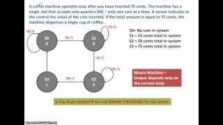
Design of a complete sequential system - Part 1 of 2
Комментарии:

good example but you missed a lot in the explanation...
Ответить
Robby ROBB
6 years ago
I think the video sucks. Actually, the diagrams are good. The coffee example was good too. But, when you begin tabulating data, you rush into jotting down zeros and ones and x's with no time to explain how you figured o

k0 = IN + q0, why?
Ответить
God bless your soul! Everything makes sense now
Ответить
HEY I NEED A HELP to design synchronous sequential network that has one input i1, one output o1, a reset signal r and a clock Clk. The output becomes 1 after the completion of the input sequence xxxxxx (. The circuit can be realized using the D flip-flop with reset (DFFR). Reset signal r to be connected with the reset input in the D flip-flops as to allow their initialization. The circuit should be from Muro type, which means that the current output of the circuit should not depend on the current input, and in fulfillment of the sequence should be gone in a special situation which shows output 1, and then from there accordingly should continue any of the other conditions without losing any entry
Ответить
you never explained how to find boolean expressions for them thats annoying. i dont understand how ko = IN + Q1
Ответить
thank you so much sir
Ответить
Hey when you make the table, you say after the last state=S3, where output=1, if another coin is inserted i.e. for in=1, shouldn't he go to state=S1 instead of state=S0.. I mean what if he wants 2 coffees??
Ответить
thanks very helpful :D
Ответить
So much work. But thanks for explaining.
Ответить
I think the video sucks. Actually, the diagrams are good. The coffe example was good too. But, when you begin tabulating data, you rush into jotting down zeros and ones and x's with no time to explain how you figured out why 0 belongs here, or why a 1 or x belongs there. I think you should edit the entire lesson with deeper explanations.
Ответить
thank you
Ответить
You can. at 12:19, J0 is either 0 or X for IN=0. and is either 1 or X for IN=1. Hence, we can directly write J0=IN.
Ответить
in 12:19 Would you please tell me, why you did not use K-maps, in order to find the boolean functions?? Thanks.
Ответить


