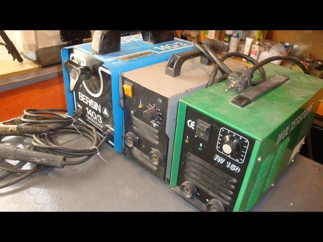
How Welding Transformers Work. Teardown and Explanation
Комментарии:

This literally answered every single question I had about the mechanisms by which transformers operate, in a remarkably well-structured format demonstrating a thorough understanding of the subject matter, making for the most time-efficient educational video I have ever seen in my life. Outstanding channel. I have never subscribed to anyone so fast before. This man is a veritable genius.
Ответить
I'll fire a quite random question here since you seem to share a common interest with me ;) I'm slowly working on getting the basic structure determined for a 3-phase 400V grid-connected device where either power factor within a very limited frequency range, or the resulting grid voltage will be increased/decreased in a IGBT AC/AC 20-30kHz fashion driving a series-coupled auto-transformer. Due to the asolutely massive scale of the componentes needed to feed several hundred kVA and and the drawn power factor from this kind of topology being reasonably sinusoidal due to lacking a DC storage leg, I have begun thinking about actually using an old fashion laminated iron/silicon 3-phase EI-transformer, and perhaps design the windings with a bit of extra air-gap between either primary and secondary, or even distancing both windings out from the core in order to increase the leakage inductance caused by the air volume inside the flux lines. I know that my efficiency will be absolutely horrible if the basic frequency that I convey would be much higher than 50Hz, but to me it feels like the total magnetic flux excursion at 20kHz pwm switching would cause a magnetic delta-ripple in the low single-digit milli-tesla or even less in a 100kg+ transformer where even a large portion of the inductive energy that takes up the ripple is inside the leakage inductance and not contributes that much to the core losses.
I am humbly asking for guidance on how I can analyze this matter better, how it connects to the various parameters of a more non-ideal transformer model (perhaps the T-model), and how well using the transformer leakage inductance in combination with only added parallell capacitance over the windings would function in the battle against EMI leakage/radiation.

I enjoy your videos but have a hard time understanding all the technical terms you use . Electronics is not my strong point.
Ответить
The amount of knowledge I'd need to even begin to understand what's being said here would probably cost tens of thousands from a university.
Ответить
Wow you are so clever 😯
Ответить
Great explanation! The only thing missing was the equivalent magnetic circuit.
Ответить
Im a welder in the states, but what you just did might as well of been Chinese because that's some language that way over my head. I can respect the amount of work and knowledge that went into this video, but I don't understand most of it
Ответить
Excellent detail in practical and theoretical regards. Thanks for sharing!
Ответить
Quite decent content. Thank you.
Ответить
Damn homie let's get back to refurbishing old vices, I feel like I did when taking a college classes I didn't understand..lol
Ответить
I'm well aware this is a relatively ancient vid, but I just had to mention how dumbfoundingly awe-struck I was watching this when I saw the pristine shape your reassembled transformers were despite them having undergone the standard practice of an E-I biopsy/disemboweling for re-purposing. My standard of "satisfactory work" done is if a transformer doesn't resemble what I view as "reanimated machinery roadkill"....which also has zero impact on whether or not I'll use whatever now-hideous thing I've mutilated, lol.
Ответить
thx!
Ответить
I have been contemplating building a spot welder (for putting tabs on batteries) based on starting out with a salvaged microwave oven transformer, and viewing videos where this was done. I see "remove the magnetic shunts" and after viewing this video now I know why.
Ответить
Great stuff. I like the way your brain works. ;-)
Ответить
Why is the primary large dia amd the secondary small, doesn't it need to be opposite for the large welding currents that need to be produced. ?
Ответить
Thank you. I think that I'm very fortunate to live in a time when I can watch teachers and researchers do their work like this. It is a very personal experience. Thank you again.
Ответить
Please commend your code ! Incredible work and video, keep them coming !
Ответить
I really liked this video, i just started my first electronics design job and now only design FPGA/analog stuff for the semiconductor test industry. now I finally got the money to do cool projects like this.
Ответить
✋...
Ответить
I'd love to see some welding training videos from you , as a maker
Ответить
It probably would have been easier and better to use an arduino board than a bare-bones microcontroller.
Ответить
I wish I was as smart as you, I try, how old are you?
Ответить
Maybe it would be easier to just put a motor and screw drive on the shunt?
Ответить
Trying to grasp the theory of the shunt:.It appears the shunt changes/redirects the flux density thru the core. Thus mechanically /physically changing position of the shunt will control/limit or increase the current available out of the secondary.
Microwave ovens have HV transformers, they have magnetic shunts in their cores. Assuming these shunts serve the same purpose, why are they needed; why would one wish to limit the output current. It would seem one would want as much as one could get? In RF output mode. Is it to protect the transformer from over current, as well as limit excessive In rush current?
Are microwave oven transformers considered “stray field transformers” because of the inclusion of shunts? And/or are the lamination orientation different in microwave transformers? I ask because I see many posts of repurposing microwave Oven transformers for welding applications. Usually the first step of repurpose is the removable of the shunts, why?

What?
Ответить
I should have been an engineer....
Ответить
I like your repurpused scrap, bessy clamps, how are they made,
Ответить
ASTONISHED BY THE QUALITY OF YOUR VIDEO :))) Best video I've seen on YT in the last years. I'm visiting your Patreon site now.
Ответить
Let’s build a battery powered welder!
Ответить
You videos are fun and educative thanks alot 💕
Ответить
I enjoy your presentations, WHAT is your NAME?
Ответить
I am NOT an electrician or something like that!! Watching this TUTORIAL makes me feel like I could become an electrician. WELL - THOUGH & PREPARED => WORK!! T-H-A-N-K-S 4 the AMOUNT of TIME spent on this! You should REALLY consider RE-UPLOADING this TUTORIAL in/auf DEUTSCH😅
Ответить
Thanks for your time, money and effort into this piece of work.
Ответить
Hey, ich hoffe ich bin richtig in der annahme Deutsch raus gehört zu haben 😁 erstmal sehr gut erklärtes und interessantes Video, werde mir die Tage ein paar mehr anschauen 👍 Weshalb ich aber hier bin ist folgendes und ich hoffe Du könntest mir eventuell bitte helfen : ich habe so ein "Baumarkt Schweißgerät" bekommen und zum reinigen geöffnet, dabei festgestellt dass die Sekundärwicklung aus Alu besteht und überlegt ob es 1. Einen Unterschied in handhabung oder Leistung machen würde 2. Sinnvoll sein könnte diese durch eine Kupferwicklung zu ersetzen und das überhaupt selbst möglich ist? Falls ja was würde sich ändern wenn ich den selben Querschnitt und Wicklungsanzahl wie die Vorhandene benutze und was ist das für eine Papier isolierung ? Ich konnte leider nirgendwo eine Antwort finden.
Ответить
Cant make AC to DC with diode and kapasitor to welding DC?
Ответить
i wish i had a super genius german to explain everything to me
Ответить
Where are you located
Ответить
I received a new einhell cen 150 euromaster tranformer welder. I want to replace the permanent cables, with ones that connect to the welder with a Dins connector. If I remove the cables how can I safely connect the internal cables to the Dins connectors on the inside pf the welder? Thank you in advance for any advice.
Ответить
The most significant difference between the 'primitive outdated' transformer welder and the others is that it is still working ! 😅
Ответить
A good question would be 'why are AC tig machines so expensive' ?
The technology is not exactly new. ( 50 / 60 years ?) Nor has the 'China factor' had that much effect on bringing down their cost to an affordable level for the home user

Thanks for the education video. I have a 9.2 KVA welding machine, with 1 large primary winding, 1 small primary winding and 1 secondary winding.
It has a 8 position switch, 0A, 55A all the way to 130A.
I suppose this uses combination of different windings through the 3P8T? switch to achieve the desired current.
It hum quite loudly, I am thinking of repurposing it to be fixed voltage PSU for audio amplifier (<3KVA), if I can solve the humming by reducing the volt per turn, and encasing it in epoxy resin.
May I seek advice from you that it would the humming be reduced significantly or I shouldn’t really bother.
I could of course, use it as a bench top lab power supply if the hums reduce, but not to audio amplifier expectations.

is there any way to rise the ocv voltage modifying the welder machine ? or rise the voltage on general? for modifying a machine and make it suitable for 6010 ellectrode? can you make this challengue ?
Ответить


