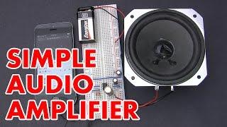
How to make an LM386 audio amplifier circuit
Комментарии:

Hi except for the supply voltage, do I need to provide a supply current for the lm 386 chip
Ответить
you never explained why the capacitor works to reduce noise
Ответить
"After I was done being a stripper"
- Afrotechmods

Neat! It would be nice to incorporate this into a bluetooth boom box!
Ответить
How can I connect two separate lm386 modules that are mono, together in bridge to achieve stereo with a single power supply?
Can this be done without a 3rd lm386 ic?

how do you connect 2 of the circuits together to make stereo? and do you need double the power supply for 2 ic's?
Ответить
I learned alot in this video, especially the dc output cancellation 😅
Ответить
Will using 5V as the supply power (VCC) give me 1/2 watt of amplified output?
Ответить
Circuit input works, but in the output sound is not coming
Ответить
thanks bro. you rerally saved me ad my lab partner bro. ou are the best. bro.
- Purdue ECE 2K7 (two thousand and 7) ( 20007) (X [bar]X [bar]VII) struggler.

Is there any way to do it with an uA741 AO?
Ответить
If the max speaker output for this circuit is only 1W, then using a 3W speaker will roast the circuit, right?
Ответить
Does this work with microphones?
Ответить
"After I was done being a stripper" 😂
Ответить
Loved the stripper remark that got you a comment and our thumbs up, that's good stuff right there
Ответить
What will be changed if I replaced the 100uf capacitor with a 220uf..
Ответить
Yooo... What you have done to "reduce the noise" is that correct? I taught you missed the concept of zobel network..you could have eliminate those noise even before entering the lm386...so correct me pls
Ответить
Just made this amplifier and it's working perfectly. I even added a potenciometer to adjust the volume. Thanks for making this video I've always wanted to make something like this
Ответить
keep the change...
Ответить
Could you please explain to me how to physically connect all the grounds together? I'm a newbie, and can't understand which wires go together, even when looking at the breadboard. It's very confusing.
Ответить
Works great 👍
Ответить
What means the vcc?
Ответить
How do I increase/lower the gain with the LM386? i.e. how do I make the amplification amount of the speaker more or less?
Ответить
What’s the name of the speaker that you use in this video?
Ответить
Where can i give a potenciometer for amplify or weaken sound?
Ответить
I can't believe how well your version works !! every circuit samples on internet sounds orrible, and yours is awersome !! I candrive a 4x12 marshall cabinet with an amazing volume
Ответить
Great vid thanks
Ответить
THANK YOU
Ответить
How to calculate the resistor and capacitor values for oscillation filtering?
Ответить
Great tutorial on the LM386. The RC network recommended on the output is called a Zobel network or Boucherot cell. The purpose of this is to modify the speaker impedance at high frequencies so that the amplifier will remain stable across its whole bandwidth. The LM386 can sound surprisingly good when it's set up just right and used within its limits.
Another interesting point about the LM386 is that it produces more distortion as the supply voltage increases if used with low impedance speakers such as most hifi units. With a 4 Ohm speaker it will perform better with a 5V supply than with higher voltages. This is because the output current it can supply is limited, so a higher supply voltage just introduces more THD without actually giving any more power to the load.

Thanks this was the simplest one...also could you let us know how much wattage speaker did you use here
Ответить
I'm so glad I found this channel, even if I wish I found it sooner.
"Now that I'm done being a stripper" 😂

How should i add 10k potentiometer to above circuit ( IC pin numbers-?)
Ответить
Hello! I have never built your circuit. However, the LM386 is famous for the following: ① The LM386 has an old and unique design, and omitting the 10KΩ to 5KΩ input volume on pin 3 will result in poor sound quality. ② The design balances the differential amplifier circuit by grounding this volume to -GND via 10KΩ to 5KΩ and grounding pin 2 to -GND. ③ Therefore, if the input volume is not needed, it is necessary to insert a fixed resistor of 10KΩ to 5KΩ between pin 3 and -GND instead. And so on (from Japan).
Ответить
after you were done being "what" ??🤣🤣
Ответить
Hello can I get the specifications of speaker? I have 8ohm 2.5 W speaker rn is it good enough?
Ответить
Thank you Sir🌹🙏🏻
Ответить
Would that work with a guitar?
Ответить
Can i ask with an 8ohm 13W resistor, can I use 5V supply or higher than that please?
Ответить
How do you zoom the noise freq at the osci? Can you explain it too?
Ответить
my chip heats up
Ответить
Will it work to amplify a crystal radio? Btw, the explanation is really easy to understand. Thank u ❤
Ответить
Where did you get the speaker and the battery case? Also how did you sauter the wires onto the cut earphone wires?
Ответить
I'm glad you left the stripper life behind you.
Ответить
I have a hard time understanding the diagrams so I use what I'm seeing in the videos as a reference. Couldn't figure out why it wasn't working. Good God I had the chip backwards.
Ответить
That series resistor capacitor on the output is not really a high pass filter, it is a Zoebel network and what that does is keep the output impedance steady across the audio spectrum by compensating for the different inductance of the speaker coil which is dependent on frequency. They are also very useful to make sure you have a good 8 or 4 ohm impedance at the crossover point of a crossover network. That is why the resistor is added in series with the capacitor. A lot of what causes the high frequency oscillation is the impedance mismatch and a Zobel network fixes that problem.
Ответить
I build this amp but it didn´t work.... no sound came out in the loud speeker... the signal was simply too low...
Ответить


